Welcome to the Forum Site › Forums › Allison 1000-2550 General Info › Size Specifications for Allison 1000-2550
Tagged: Allison Size Specs
- This topic has 0 replies, 1 voice, and was last updated 4 years, 8 months ago by
 Jason D.
-
AuthorPosts
-
October 16, 2020 at 6:03 pm #462
 Jason DKeymaster
The Allison is much bigger in physical size than most transmissions, the Allison’s length will most likely require driveshaft modifications and will also require the cross member to be moved back. The other challenge is the
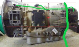
height of the middle and rear part of the transmission. 4×4 versions are the same as 2 wheel drive transmissions in regard to the diameter of the rear clutch housing. If you can measure your current transmission in your truck from the center of the output shaft (or calculated center) to your floor pan you need at least 7” for it to fit without modifications to the floor pan
(1” clearance may be just barely enough).As you may realize, ideally you want the Allison output shaft center line in the same place as your current transmission. It is often possible to bend your floor pan up a bit with a floor jack and a block of wood, but no more than 2-3”. On 4×4 versions, from the top of the transmission cross member (where the mount rests) to the center line of the output shaft is about 6 1/8”.
Cooler lines are 5/8”- I don’t recommend depending on remote mounted coolers with fans. Those are great for an auxiliary cooler, but if the fan goes out you may not notice. Many factory trucks that get an Allison swap have 1/2” line coolant to fluid coolers in series with an air to fluid cooler in front of the radiator. These work fairly well in moderate climates with moderate loads, but if you live in a hot climate or tow heavy, a fan type add on is a good idea in addition to those. Derale makes a big cooler with a fan that fits this description.
4×4 length from face of bellhousing to end of transfer case mating surface is 30”
From bellhousing to mount perch centerline is 28 ¼”
Top rear of trans to bottom of mount is 12 1/8” for 4×4 version.

Shown above in green is the typical harness routing from the inside driver side frame rail, across thetransmission crossmember, and up over the back of the trans to the main connector. The smaller lines show how I typically break out for the speed sensor wiring.Attachments:
You must be logged in to view attached files. -
AuthorPosts
- You must be logged in to reply to this topic.